Powered by Modern Robotics

0 $0.00

Cart

No products in the cart.
Shop

HiTechnic NXT SuperPro Prototype Board

$26.95

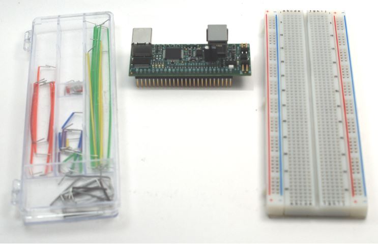
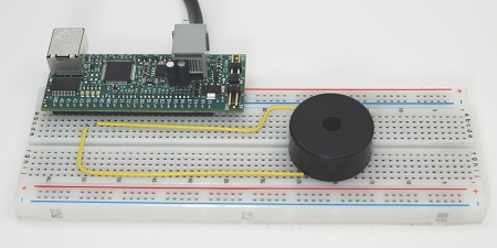
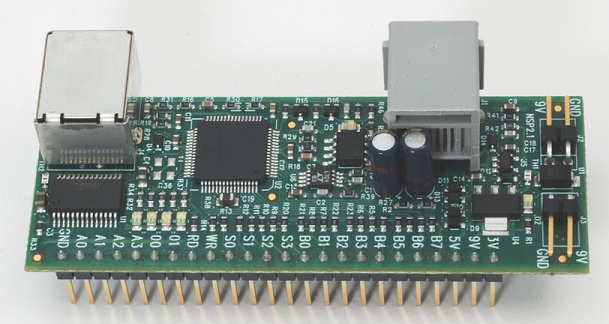
Create your own sensors and build your own electronic circuits with the HiTechnic SuperPro Prototype Board. The SuperPro Board is designed to plug into a solderless breadboard giving you the perfect platform to create your own NXT sensors. The HiTechnic SuperPro Prototype board connects to an NXT sensor port so your NXT programs can send commands to and read data from the SuperPro. NXT programming is easy with the HiTechnic NXT-G SuperPro Prototype programming block as well as with NXC, RobotC or LabVIEW. The SuperPro will also connect directly to a PC using its USB port for high speed I/O. With the SuperPro on-board program environment you can write programs on a PC using SuperPro C (SPC) and download and run your programs directly on the SuperPro. The SuperPro has 8 digital input/output pins, 4 analog inputs, 6 strobe outputs, 2 analog outputs, as well as two on-board LEDs.

Out of stock

Join the waitlist to be emailed when this product becomes available

SKU: SPR2010 Category:

Description

HiTechnic SuperPro Sensor for LEGO Mindstorms NXT

Introduction

The HiTechnic SuperPro Sensor creates an easy-to-use platform for building your own sensors and safely experiment with electronic that can be directly connected to the LEGO NXT via an NXT sensor port. For applications that do not require an NXT the HiTechnic SuperPro Sensor can be connected to your PC via the onboard USB port. The SuperPro Sensor firmware includes features to interface seamlessly with the NXT to respond to commands from NXT programs developed in NXT-G, LabView, NXC, RobotC and other languages. The SuperPro Sensor also supports a powerful onboard program environment that enables programs developed in C using the SPC programming environment to be downloaded and run on the SuperPro.

The SuperPro Prototype Board is designed to connect to a solderless breadboard allowing reuse of electronic components.

Specifications

  • 3 Power Outputs
    • 3.3 volts regulated at 15mA from NXT
    • 5.0 volts regulated at 8mA from NXT
    • 9v volts unregulated at 8mA from NXT
    • 3.3 volts, 5.0 volts and 9 volts from external battery connection if applied
  • 4 Analog Inputs (A0 – A3)
    • 0 – 3.3 volt range
    • 10 bit A/D conversion
  • 8 Digital I/O (B0 – B7)
    • Individually configurable as inputs or outputs, 0 or 3.3 volts
    • 220 ohm output series resistor
  • 2 Analog Outputs (O0, O1)
    • 0 – 3.3 volts via 10 bit D/A conversion
    • 7 analog modes:
      1. DC voltage level
      2. Sine wave
      3. Square wave
      4. Positive going sawtooth
      5. Negative going sawtooth
      6. Triangle wave
      7. PWM voltage
    • 220 ohm output series resistor
  • 6 Digital Strobe Outputs (S0 – S3, RD, WR)
      • 4 can be set to logic 0 or 1 (0 or 3.3v)
      • 1 pre-configured read strobe
      • 1 pre-configured write strobe
    • 220 ohm output series resistor
  • Onboard memory
    • 12k user RAM
    • 56k user program FLASH
    • 1Mb external storage FLASH
  • Onboard Firmware Features
    • NXT I/O data and command connection
    • USB I/O
    • Onboard program execution
    • Multiple simultaneous user processes
    • Onboard datalogging

Note that the digital, strobe, and analog outputs all have 220 ohm series resistors. This resistor effectively limits the current that is available from each output. The total current output at the 3.3v level (sourced current) should be 50mA from all outputs (D, A and 3.3v output). In the sink case, the total current can be 80mA total max.

I2C Interface

The SuperPro uses I2C device address of 0x10.
Address
Type
Field
00 – 07H
chars
Sensor version number
08 – 0FH
chars
Manufacturer
10 – 17H
chars
Sensor type
42-43H
byte
Analog input A0; upper 8 bits, lower 2 bits
44-45H
byte
Analog input A1; upper 8 bits, lower 2 bits
46-47H
byte
Analog input A2; upper 8 bits, lower 2 bits
48-49H
byte
Analog input A3; upper 8 bits, lower 2 bits
4CH
byte
Digital inputs (bits B0 – B7)
4DH
byte
Digital outputs (bits B0 – B7)
4EH
byte
Digital input/output control (bits B0 – B7)
50H
byte
Strobe output (bits S0 – S3)
51H
byte
LED control(0=none, 1=Red, 2=Blue, 3=Red and Blue)
52H
byte
Analog output O0 mode
53-54H
byte
Analog output O0 frequency; msb, lsb
55-56H
byte
Analog output O0 voltage; upper 8 bits, lower 2 bits
57H
byte
Analog output O1 mode
58-59H
byte
Analog output O1 frequency; msb, lsb
5A-5BH
byte
Analog output O1 voltage; upper 8 bits, lower 2 bits

The Sensor version number field returns the revision number in the format “ Vn.m” where n is the major version number and m is the revision level.

The Manufacturer field contains “HiTechnc”.

The Sensor type field contains “Proto ”.

The A0–A3 analog inputs contain the upper 8 bits in the first byte and the lower 2 bits in the second byte.

The Digital inputs field returns the state of the eight digital signals in bits 0–7.

The Digital outputs field sets the state of the six digital signals which have been configured as outputs.

The Digital input/output control field configures the direction of the eight digital pins B0-B7. Set the corresponding bit to 0 for input and 1 for output.

The Strong output field sets the state of the 4 general purpose strobe outputs, pins S0-S3.

The LED control field sets the state of the two on-board LEDs. Bit 0 for red LED and Bit 1 for blue LED.

The Analog mode field sets the analog mode of the analog output O0 or O1.

The Analog frequency field sets the analog frequency, 1-8191. msb, lsb.

The Analog Voltage field sets the voltage level of the analog output O0 or O1. upper 8 bits, then lower 2 bits. 10-bit value corresponds to the range 0-3.3v.

The prototyping sensor board electronics derives a stabilized 3.3v internal supply from either the NXT supplied 4.3v source or an internal 4.3v source derived from an external 9v supply. Use of a low dropout regulator will permit continued operation with supply input down to 3.6v. Operation below 3.6v input will be unreliable. The board electronics also derives a stabilized 5.0v from the supplied 9v source. The 9v may be either obtained from the NXT or an external 9v source connected between the 9v and GD connections.

Programming

Programs for the HiTechnic SuperPro Prototype Board can be developed using any of the popular NXT programming languages.

NXT-G SuperPro Sensor Programming Block

The SuperPro NXT-G programming block makes it easy to write programs that interface with the SuperPro board. The configuration panel allows selecting an action to read or write to any of the analog or digital ports.

All the parameters can also be used by using data wires to pass the data to the SuperPro.

  1. This plug wires the port number for the NXT Port used for the SuperPro.
  2. This plug wires the action to be performed by the block. The actions are numbered starting with zero:
    1. Read Analog Port
    2. Read Digital Port
    3. Write Digital Control
    4. Set Strobe control
    5. LED Control
    6. Analog Output
  3. This plug wires the general input value. This can be the digital mask, digital write value, digital control, strobe control, LED control, and the analog output voltage level depending on the selected action.
  4. This plug is the analog port used for both the input A0 – A3 and the output O0 and O1 depending on the action.
  5. This plug wires the analog mode for the Analog Output action. The analog modes are numbered starting with zero:
    1. DC
    2. Sine Wave
    3. Square Wave
    4. Positive Sawtooth
    5. Negative Sawtooth
    6. Triangle Wave
    7. Pulse Width Modulation
  6. This plug wires the frequency for the analog output in Hertz and can be in the range 1 to 8191.
  7. This plug wires the comparison mode used for the two read actions. The Compare modes are numbered starting with zero:
    1. <
    2. >
    3. =
  8. This plug wires the value used for the comparison.
  9. This output plug holds the value when used with one of the read actions.
  10. This output plug holds the Yes/No result of the comparison when used with one of the read actions.

LabVIEW

Use LabVIEW 2009 or LabVVIEW for LEGO Mindstorms (2010) for programming the NXT to interface with the SuperPro. VIs allow reading and writing to both the analog and digital ports as well as to control the 2 onboard LEDs. Here is an example of a program to read the analog and display the result on the NXT screen:

NXC and SPC

The latest test release of BricxCC/NXC, dated 10/24/2011 or later, includes support for programming the NXT to interface with the SuperPro as well as writing programs in SPC, SuperPro C, that run right on the SuperPro board. See NXC/NBC/SPC site for more information.

RobotC

It is also possible to interface with the SuperPro using RobotC version 2.0 or higher.

Caution

The Prototype sensor and electronic components used to create circuits may be damaged by static discharge so care must be taken when handling the prototype board and components to avoid static.

Additional information

Weight .0660 lbs
Dimensions 6 × 5 × 1 in

Robot C

The RobotC driver suite supports HiTechnic products for RobotC 4.x and RobotC 3.x. Select the corresponding repository at the link below and download the zip file.

https://github.com/botbench

Downloads

No downloads found!